Individual Row Hydraulic Downforce (IRHD)
 IRHD system
IRHD has been specifically designed to meet the needs of producers that are looking to adjust to the toughest field conditions and provide maximum yield potential from field to field, season after season. IRHD works as a closed-loop downforce system that reacts quickly on an individual row basis to changing soil conditions supporting increased ground contact, which can lead to improved seed depth consistency. When setting planter downforce margin, the system will apply the needed downforce by row to maintain ground contact. From the factory, the margin will be set at 45.4 kg (100 lb), changes may be required based on varying field conditions.
The system allows operators to maintain gauge wheel ground contact leading to desired seed depth placement. IRHD can adjust five times per second and make adjustments of 45.4 kg (100 lb) in less than a second. The system has a total range of applied downforce from 22.7 kg (50 lb) to 204.1 kg (450 lb) and utilizes the power beyond circuit on the tractor. IRHD is 58 percent faster than the active pneumatic downforce solution. Fast reaction and increased ground contact can lead to improved emergence. With uniform emergence, some studies have shown a yield impact from 5 percent to 9 percent.
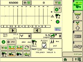
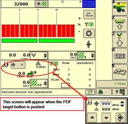
IRHD is controlled through the display with SeedStar™ 3 HP or SeedStar 4HP. As shown below, operators can view ground contact or applied downforce using the toggle button.
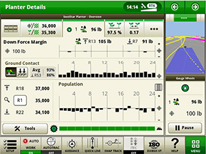 IRHD screen showing the ground contact graph through SeedStar 4HP
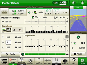 IRHD screen showing the applied downforce graph with SeedStar 4HP
Hydraulically driven compressor
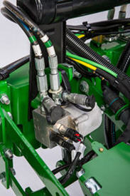
 Pneumatic valve
The hydraulically driven air compressor can deliver up to eight times the air flow when compared to the electric compressor, allowing for more and faster downforce changes to be made. This more robust design features a 37.8-L (10-gal.) storage tank across all models with active downforce.
At approximately 15.1 L/min (4 gpm), hydraulic demands are low and ties into the machine’s lift and Central Commodity System (CCS™) hydraulic circuit so it does not require any additional selective control valves (SCVs). The SeedStar XP, SeedStar 3 HP, and SeedStar 4 HP monitoring systems work with the compressor. SeedStar 3 HP and SeedStar 4 HP monitoring systems work with the compressor and valve assembly to regulate air to downforce springs, enabling the active control, pneumatic closing wheels, and pneumatic row cleaners.
Row-unit downforce planter run page
 SeedStar XP downforce planter run page
Active downforce control is integrated into SeedStar XP, SeedStar 3 HP, and SeedStar 4 HP monitoring systems.
Margin is the amount of weight riding on the depth gauge wheels that ensures desired firming of the seedbed as set by the operator.
Once a target margin has been defined, enter the value into the display and let active downforce do the rest. The system will actively adjust the air pressure in the air bags to maintain a constant margin across the planter. The changes in air pressure will change the amount of downforce placed on the row-unit, compensating and reacting for varying conditions through the field whether it is different tillage practices, soil types, or moisture.
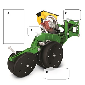 Downforce and margin example
- A - Margin – amount of additional downforce applied to a row-unit above and beyond what is required for penetration to achieve planting depth. This additional weight will ride on the depth gauge wheels.
- 54.4 kg (120 lb) + 36.3 kg (80 lb) = 90.7 kg (200 lb) – 68 kg (150 lb) = 22.7 kg (50 lb) of margin
- B - Weight of row-unit - 54.4 kg (120 lb)
- C - Downforce – force that is applied to the row-unit by the air bag circuit - 36.3 kg (80 lb)
- D - Resistance from soil - 68 kg (150 lb)
Margin video references:
Understanding Margin
Using Set Point downforce
Using Active Pneumatic downforce
SeedStar 4HP: Downforce
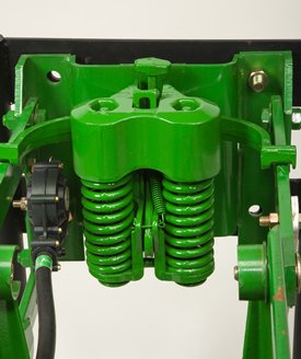
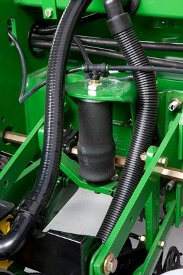 Pneumatic downforce spring
Each row-unit has a single rubber air bag located between the parallel arms. The air bags are hooked in parallel so that air can be added or released from all rows at once from one location.
The individual pneumatic downforce air bag assemblies, air compressor units, and 9.5-mm (3/8-in.) delivery lines are also available as an attachment for field conversion.
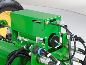
 Active downforce compressor assembly
A hydraulically driven compressor works with the SeedStar XP, SeedStar 3 HP, and SeedStar 4 systems to automate downforce control. Just set the row-unit target margin value and the active pneumatic downforce system works automatically. The system will make sure the planter maintains this value, achieving precise soil penetration, and consistent planting depth, without sidewall soil compaction. From the factory, the system is set at 45.4 kg (100 lb) target downforce margin but may be modified for varying field conditions. This frees the operator from constantly making manual downforce adjustments as conditions change.
This system offers a split-rank control feature for 1795 and DB Split-Row Planters. On split-row planters, active downforce will control the front and rear rows independently. This compensates for differing downforce requirements between the ranks that can be caused by things like different tillage or insecticide attachments and will help maintain an accurate planting depth and consistent margin across all the rows.
Active pneumatic downforce is available as factory installed or as an attachment for field conversion.
Set point row-unit downforce
 Pneumatic downforce control in GreenStar 2 Display
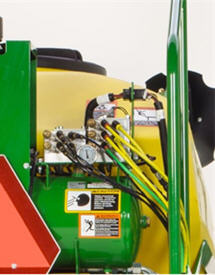
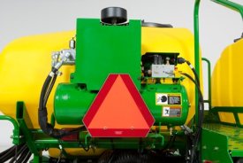
 Air compressor mounted on 1775NT outer hitch
On set point, the air compressor will be mounted on the outer hitch or frame assembly. Since the electric air compressor assembly is mounted on the outer hitch (as noted in the picture above) or frame, adjustments for row-unit downforce and related system pressures will be made electronically with the GreenStar display.
When adjusting the amount of row-unit downforce using the GreenStar display, the operator will select the amount of downforce (kg [lb]) to be applied across the planter. Depending on the soil conditions at hand, the operator might need to adjust the relative amount of row-unit downforce being applied during the planting operation. The integrated pneumatic downforce controls within the GreenStar display will only allow for set-point operation and not automatic control as the planter is operating in different soil conditions. The pneumatic downforce system does not have the capability to automatically adjust downforce.
Pneumatic downforce provides convenient, simple adjustment of downforce for the whole planter from one location. The amount of downforce applied is infinitely adjustable from 6.8 to 181.4 kg (15 to 400 lb). Pneumatic downforce provides more consistent downforce throughout the range of row-unit travel than mechanical spring downforce systems.
Features include:
- 9.5-mm (3/8-in.) air delivery line instead of the 6.4-mm (1/4-in.) line used on model year 2010 and older planters.
- Air compressor assembly increased duty cycle. With this compressor, it provides a 47 percent increase in maximum air flow delivery compared to the prior air compressor.
- Pneumatic air bags with 9.5-mm (3/8-in.) air line inlets that have greater durability.
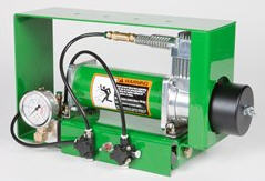 Pneumatic downforce compressor and gauge
An improved compressor is used to charge the pneumatic system. This compressor can be located on the planter frame or in the tractor cab if desired. A gauge at the compressor indicates the amount of downforce being applied.
Integrated pneumatic downforce system
The functional features of the integrated system are the same as the standard pneumatic system, explained above, with the addition of control through the GreenStar display.
Heavy-duty adjustable downforce springs
 Heavy-duty adjustable downforce spring
Planter row-unit downforce is an important factor to ensure consistent and proper depth control. The heavy-duty adjustable downforce feature provides up to 181.4 kg (400 lb) of downforce. There are four settings available to allow the operator to choose the amount of downforce required for the condition: 0 kg (0 lb), 56.7 kg (125 lb), 113.4 kg (250 lb), and 181.4 kg (400 lb).